


TMMY Scale Composites 27% (120") Cessna 182 TC Skylane.
 05-07-2021, 01:00 PM
#101

Join Date: Jul 2007
Location: Frederick, MD
Posts: 615
Likes: 0
Received 0 Likes
on
0 Posts
This -----> "drill them perpendicular to the surface and achieve down thrust by using washers."
What I do is start with three small washers on the UPPER left side (left side being on the LEFT SIDE)
between the engine itself and the respective standoff. LOWER left I use two small washers. UPPER right I use two
small washers, and LOWER right no washers.
I have no experience with hard plastic/nylon standoff spacers which it appears you're using. All of mine are
aluminum. If those hold up well through repeated use, you should be ok long term. And, are you positive that
there is no right-and-down thrust built into the Cessna's firewall?
Caveat....I noticed that your cowl is "fixed" to the fuselage whereas most gasser's cowls can be "adjusted" TO
the centerline of the crank AFTER the down-and-right adjustments to the engine. I would think that with the larger
size of the 182's cowl, that the engine's crankshaft might possibly not be in complete alignment with the center
opening in the cowl after addition of the washers. Personally, it would not be as big a concern for me due to what I
would think is a miniscule offset when seen straight on. The backplate on the spinner would hide some of that anyway.
But....I would first fly the plane sans cowl with the above-mentioned washers in place to see how much right rudder
is STILL required at takeoff with the engine you're using, plus in-flight, how does the plane track at full and half throttle
settings. Is it still turning left? Does right rudder TRIM trim this out without using the aileron trim for straight-and-level?
You'll undoubtedly need several flights to get the Cessna trimmed correctly (maybe more or less washers as well) just
be sensitive to HOW it is turning in flight at most throttle settings. Different engines will require more or less down-and-right
thrust due to several factors with each individual engine brand and size.
Thanks for your in-depth explanation of how to achieve down and right thrust angle of gassers or glow rc airplanes. This is so helpful and insightful. I did employ the use of washers if you look closely at the pictures I attached however more of them are required to angle a tad bit more.
Right thrusts on the other hand has not been added since I will like to try out the use of the elevators right trim tab which I had customized and will operate remotely with the use of a dial nob on my transmitter.
If I am not mistaken I believe this is how the full scale Cessna's trim to counter the tendency to roll or veer to the left... Correct me if I'm wrong.
Plastic spacers is what I usually use to shave off a bit weight since most of my builds end up being nose heavy. They work out great and currently use similar setup on my Hangar 9 Cessna 182, powered with an OS FT-160 Gemini twin cylinder four stroke.
Last edited by RonTins; 05-07-2021 at 01:03 PM.
 05-07-2021, 01:20 PM
#102

Join Date: May 2008
Location: Ruralarea,
AZ
Posts: 408
Likes: 0
Received 0 Likes
on
0 Posts
Ah no, you're wrong. (I'm a full-size aircraft owner/pilot since '78). The trim tab on your elevator is not what corrects for the
right turning tendencies of an aircraft. They are torque, prop wash, p-factor, etc. that cause the nose of the aircraft to rotate
(turn) left. Ailerons "bank" an aircraft, the rudder turns an aircraft, and the elevator in simple terms makes it go up and down.
(Yes, I know that power is altitude...I said in SIMPLE terms).
 05-07-2021, 03:32 PM
#103
Join Date: Jul 2007
Location: Frederick, MD
Posts: 615
Likes: 0
Received 0 Likes
on
0 Posts
Ah no, you're wrong. (I'm a full-size aircraft owner/pilot since '78). The trim tab on your elevator is not what corrects for the
right turning tendencies of an aircraft. They are torque, prop wash, p-factor, etc. that cause the nose of the aircraft to rotate
(turn) left. Ailerons "bank" an aircraft, the rudder turns an aircraft, and the elevator in simple terms makes it go up and down.
(Yes, I know that power is altitude...I said in SIMPLE terms).
right turning tendencies of an aircraft. They are torque, prop wash, p-factor, etc. that cause the nose of the aircraft to rotate
(turn) left. Ailerons "bank" an aircraft, the rudder turns an aircraft, and the elevator in simple terms makes it go up and down.
(Yes, I know that power is altitude...I said in SIMPLE terms).
Thank you.
05-07-2021, 04:25 PM
#104
Join Date: May 2008
Location: Ruralarea,
AZ
Posts: 408
Likes: 0
Received 0 Likes
on
0 Posts
The "trim tab" trims the aircraft for level flight. Say you're flying a 182 and have to hold a bit of back pressure to keep the plane
from descending. You simply "dial in" a bit of NOSE UP with the trim "wheel" located to the right of your right leg about mid way
down. See the pic. One trims an aircraft in three dimensions, it's a balancing act but becomes second nature pretty quickly. The
trim wheel pictured is for the elevator. To the right is the one for the rudder. On some aircraft, the entire elevator gets trimmed
with the trim wheel.....no trim tab. On RC planes, we trim with the trim switches located adjacent to the corresponding stick.
05-08-2021, 07:15 AM
#105
Join Date: Jul 2007
Location: Frederick, MD
Posts: 615
Likes: 0
Received 0 Likes
on
0 Posts
The "trim tab" trims the aircraft for level flight. Say you're flying a 182 and have to hold a bit of back pressure to keep the plane
from descending. You simply "dial in" a bit of NOSE UP with the trim "wheel" located to the right of your right leg about mid way
down. See the pic. One trims an aircraft in three dimensions, it's a balancing act but becomes second nature pretty quickly. The
trim wheel pictured is for the elevator. To the right is the one for the rudder. On some aircraft, the entire elevator gets trimmed
with the trim wheel.....no trim tab. On RC planes, we trim with the trim switches located adjacent to the corresponding stick.
05-13-2021, 05:02 PM
#106
Join Date: Jul 2007
Location: Frederick, MD
Posts: 615
Likes: 0
Received 0 Likes
on
0 Posts
After several tries to center engine to the cowl prop opening I decided to fabricate a downward thrust angle on which the engine bolts onto. May I have feedback as to whether the thrust angle is satisfactory or too much?


Downward thrust angle of at least 8 degrees to align with cowl

Am I being a little too picky or is the distance of the spinner backplate a bit too far?
Downward thrust angle of at least 8 degrees to align with cowl
Am I being a little too picky or is the distance of the spinner backplate a bit too far?
05-13-2021, 08:35 PM
#107
Join Date: May 2008
Location: Ruralarea,
AZ
Posts: 408
Likes: 0
Received 0 Likes
on
0 Posts
FW,
This is how I do ALL my gas engine setups. Keeping in mind NONE of my engines are larger than 35cc:
What I do is start with three small washers on the UPPER left side (left side being on the LEFT SIDE)
between the engine itself and the respective standoff. LOWER left I use two small washers. UPPER right I use two
small washers, and LOWER right no washers. SEE MY PIC ON POST #100.
Also, if this 120" Cessna 182 were mine, I would spread the load at the firewall AND the plywood plate you made using
fender washers readily available at most hardware stores. The ones with the small hole in the middle just big enough
to pass the socket head cap screws through. OD would be "about" an inch. See the pic with yellow circles. And, see the
pic with my standoffs bolted to the firewall of my Cessna 152. You will see the fender washers. (Disregard the aluminum
plate as I attached it to strengthen the firewall in this particular model).
Lastly, and this is ONLY my opinion.....I personally would not have angled the engine the way you have. It "appears" from
what I can see that you have angled the engine downward as you said, "Eight degrees." IMO, that is too much and you
have not taken care of the right thrust angle for aesthetic purposes.
Again, if this were my 182, I would leave the cowl off entirely, place washers as I have suggested, and fly the plane then
adjust from there. Also, I did not see LOCK washers between the socket "head" and respective washer. Use blue
Locktite as well in all metal-to-metal contact.
Question - how many CCs is your engine?
05-14-2021, 06:31 AM
#108
Join Date: Jul 2007
Location: Frederick, MD
Posts: 615
Likes: 0
Received 0 Likes
on
0 Posts
Thanks for your analysis Kim.
I initially started the angling of the engine using washers, three of them however there appeared to be no noticeable changes in downward thrust angle. This caused an increase in spacers one at a time until six (6). Using six (6) washers on the two top stand offs and one (1) each on the bottom two stand offs with blind nuts to secure the engine with socket screws, "8-32", I noticed the screws and blind nuts would stripe every time the engine is removed. Having all four at the same angle would prevent stripping and hence the reason this setup was applied.
One inch outer diameter washers with the hole small enough to insert an 8-32 socket screw is a good suggestion to use to spread the load on the firewall from the stand offs and will get a few of these from my local ace hardware store.
Engine pictured in above posts is an OS FF-320 Pegasus with 53ccm of engine displacement. Weighs in at a little over 5 pounds with onboard starter motor and starter ring gear to turn the prop shaft for starting.
 05-14-2021, 04:33 PM
#110
Join Date: Jul 2007
Location: Frederick, MD
Posts: 615
Likes: 0
Received 0 Likes
on
0 Posts
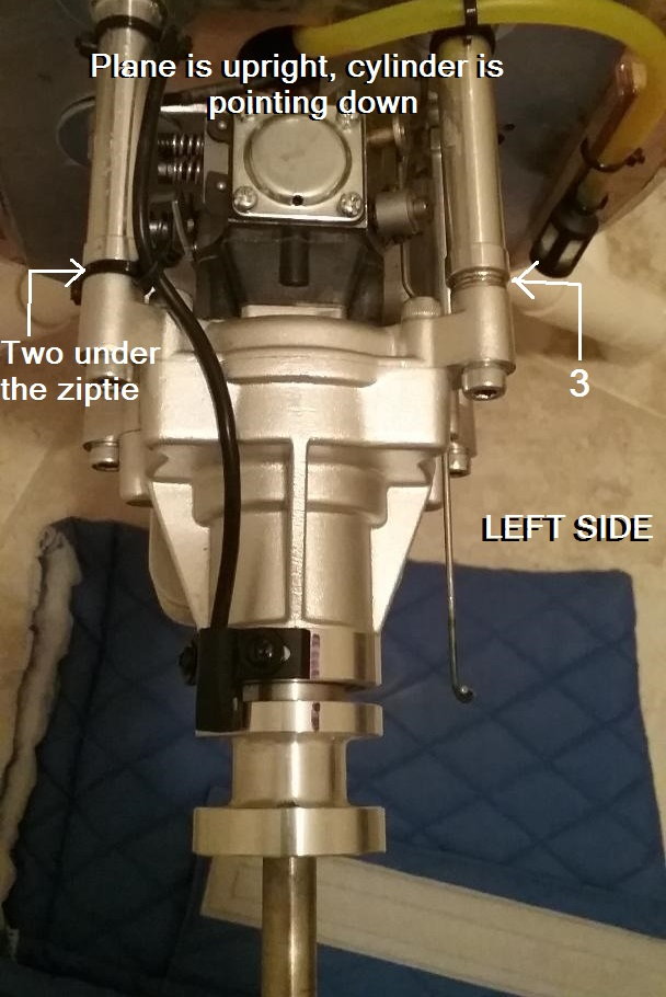
The stand offs are 77.14mm long and cap screws your arrows point to are secured using blind nuts on the cabin side of the firewall. I'll go for lock nuts to secure the engine stand offs socket (cap) screws as working with blind nuts have been a pain in the rear.
I'll shorten the stand offs about 6 mm to close the gap between the cowl and spinner and also consider adding rubber bushings to reduce engine vibration as well.
I'll shorten the stand offs about 6 mm to close the gap between the cowl and spinner and also consider adding rubber bushings to reduce engine vibration as well.
Last edited by RonTins; 05-14-2021 at 04:36 PM.
05-14-2021, 09:43 PM
#111
Join Date: May 2008
Location: Ruralarea,
AZ
Posts: 408
Likes: 0
Received 0 Likes
on
0 Posts
The stand offs are 77.14mm long and cap screws your arrows point to are secured using blind nuts on the cabin side of the firewall. I'll go for lock nuts to secure the engine stand offs socket (cap) screws as working with blind nuts have been a pain in the rear. I'll shorten the stand offs about 6 mm to close the gap between the cowl and spinner and also consider adding rubber bushings to reduce engine vibration as well.
threaded on both ends plus four (4) 1/2" heavy nylon spacers which should give you exactly the spacing you're after. I think the threads
are either 10/32 or M5. This setup "should" yield close to your 71mm and eliminate a whole bunch of unnecessary parts, IMHO.
What I would do is reach up under the glareshield (dashboard) and yank out the blind nuts. Using long enough socket head cap screws
on the interior side of the firewall with lock washers AND fender washers, push these 3-parts thru the respective four holes in the firewall.
On the engine side of the firewall, slip four (4) fender washers onto the socket head cap screws threads then attach the standoffs screwing
them onto the cap screw threads with a dab of blue Locktite.
On the four standoffs ends that the engine gets attached to is where the 1/2" spacers go. Engine side of each spacer is where you'll place
the "down-n-right" washers. Your statement that your engine does not look "canted" enough using the washer's pictures I've shown you, is
not valid. I would suggest drawing a straight line and then another line off one end of the first line to simulate what 2 and 3 degrees looks like.
These "degree" measurements are miniscule! Yes, they are, but the engine WILL respond accordingly. Please ask another RCer there where
you live (a club member maybe) who has experience with gassers for their opinion too. As I stated in another post before this one, canting your
engine down and to the right, 3 and 2 degrees, might only be discernible to you with the cowl in place after all is said and done.
If you'd like to have the standoffs and spacers, send me a PM with your address. They're on me!
Last edited by V35BFLYER; 05-14-2021 at 09:46 PM.
05-19-2021, 07:23 AM
#112
Join Date: Jul 2007
Location: Frederick, MD
Posts: 615
Likes: 0
Received 0 Likes
on
0 Posts
If you're interested....I have several (10 to 12) aluminum standoffs, most of which are 2.50" each. I could send you 4 of them, no charge,
threaded on both ends plus four (4) 1/2" heavy nylon spacers which should give you exactly the spacing you're after. I think the threads
are either 10/32 or M5. This setup "should" yield close to your 71mm and eliminate a whole bunch of unnecessary parts, IMHO.
What I would do is reach up under the glareshield (dashboard) and yank out the blind nuts. Using long enough socket head cap screws
on the interior side of the firewall with lock washers AND fender washers, push these 3-parts thru the respective four holes in the firewall.
On the engine side of the firewall, slip four (4) fender washers onto the socket head cap screws threads then attach the standoffs screwing
them onto the cap screw threads with a dab of blue Locktite.
On the four standoffs ends that the engine gets attached to is where the 1/2" spacers go. Engine side of each spacer is where you'll place
the "down-n-right" washers. Your statement that your engine does not look "canted" enough using the washer's pictures I've shown you, is
not valid. I would suggest drawing a straight line and then another line off one end of the first line to simulate what 2 and 3 degrees looks like.
These "degree" measurements are miniscule! Yes, they are, but the engine WILL respond accordingly. Please ask another RCer there where
you live (a club member maybe) who has experience with gassers for their opinion too. As I stated in another post before this one, canting your
engine down and to the right, 3 and 2 degrees, might only be discernible to you with the cowl in place after all is said and done.
If you'd like to have the standoffs and spacers, send me a PM with your address. They're on me!
Over the past few days, I have swapped up my mounts for shorter ones and now have the distance between the cowl ring and spinner backplate reduced tremendously, from around 6.35 mm to about 3mm which was quite bothersome visually.
I also picked up one-inch washers as recommended and is currently installed in between the outside of the firewall and the first four set of standoffs that attaches the mount plate I created with the canted plates on which the engine mounts are bolted onto. I am confident this setup will work as the engine appears aligned and is centered with the cowling on. What I need to acquire now are longer 8-32 socket screws as the current ones (4 inches) appear short due to the canted plates used.
Due to my scale preferences on most of my builds, my airplanes end up being on the heavy side and with this in mind I usually prefer my standoff mounts in plastic as much as possible. This has worked out great in the past and I am confident it will hold up in this application, implementing engine thrust angles at 3 degrees down and 2 degrees to the right as recommended using my plate design.
05-26-2023, 02:46 PM
#113
Join Date: Jul 2007
Location: Frederick, MD
Posts: 615
Likes: 0
Received 0 Likes
on
0 Posts
This thread has been dormant for quite a while and can believe that others have not been enjoying their bird or sharing pictures of their build progress. After years of family life getting in the way, I plan on resurrecting mine very soon.
 05-28-2023, 02:16 PM
#115
Join Date: May 2008
Location: Ruralarea,
AZ
Posts: 408
Likes: 0
Received 0 Likes
on
0 Posts
Well......it's about TIME! Wondered what the heck happened with that gorgeous
120" Cessna 182 of yours!
I did correspond with Tommy a year or so ago to see if he'd sell direct. And he will.
But, now with container freight, and all shipping charges having gone thru the roof,
it would be extremely expensive in my opinion to nine-yard one of these now. Plus
even if I had the dough to buy one, I don't have a vehicle big enough.
And I'm amazed that we have not seen anyone on RCU or FG or RCG assembling
one of these and flying it in the last few years. These 120" 182s and the bigger ones
are just an unbelievable RC airplane!
So please get to it! I'm sure there will be a lot of us following along as yours finally
gets finished.
All best,
Kim in AZ
05-28-2023, 06:15 PM
#116
Join Date: Jul 2007
Location: Frederick, MD
Posts: 615
Likes: 0
Received 0 Likes
on
0 Posts
 05-28-2023, 06:24 PM
#117
Join Date: Jul 2007
Location: Frederick, MD
Posts: 615
Likes: 0
Received 0 Likes
on
0 Posts
Well......it's about TIME! Wondered what the heck happened with that gorgeous
120" Cessna 182 of yours!
I did correspond with Tommy a year or so ago to see if he'd sell direct. And he will.
But, now with container freight, and all shipping charges having gone thru the roof,
it would be extremely expensive in my opinion to nine-yard one of these now. Plus
even if I had the dough to buy one, I don't have a vehicle big enough.
And I'm amazed that we have not seen anyone on RCU or FG or RCG assembling
one of these and flying it in the last few years. These 120" 182s and the bigger ones
are just an unbelievable RC airplane!
So please get to it! I'm sure there will be a lot of us following along as yours finally
gets finished.
All best,
Kim in AZ
120" Cessna 182 of yours!
I did correspond with Tommy a year or so ago to see if he'd sell direct. And he will.
But, now with container freight, and all shipping charges having gone thru the roof,
it would be extremely expensive in my opinion to nine-yard one of these now. Plus
even if I had the dough to buy one, I don't have a vehicle big enough.
And I'm amazed that we have not seen anyone on RCU or FG or RCG assembling
one of these and flying it in the last few years. These 120" 182s and the bigger ones
are just an unbelievable RC airplane!
So please get to it! I'm sure there will be a lot of us following along as yours finally
gets finished.
All best,
Kim in AZ
It's a shame shipping prices are through the roof now it almost makes it impractical to get one of these beautifully made birds, be it the 120" or it's bigger sister version.
I am working on wiring the navigation and strobe lights in both wings. I didn't like the factory installed navigation lights as they did not look scale so I purchased a set of lights from UniLights. Also want to place fuel tanks, one in each wing so it is filled just like the real Cessna 182's. I know it's quite ambitious on my part but I'm curious to see how it will work.
05-29-2023, 05:44 PM
#118
Senior Member
Thanks all for sharing the information
To be clear for the information we collected recently for intl shipping from Thai to worldwide, the customer can contact your local freight broker and see how they charge. It is not cheap. For sea freight to New Zealand, the sea freight cost for 157" Cessna 185 is over $1000 USD which was charged by the freight broker. The production team and Austars only want to help and get the lower cost for you. if you can find a lower cost, just let us know.
Cheers
Teamaustars
06-04-2023, 10:48 AM
#120
Join Date: Jul 2007
Location: Frederick, MD
Posts: 615
Likes: 0
Received 0 Likes
on
0 Posts
I cut off the aileron control horns as the ones installed from factory was not symmetrical to the other wing and also distance to the servo arms were a bit off. New horns ordered from dreamworksrc were just installed yesterday just as I would have like the. My question is do you all use 30 minute epoxy glue for ailerons for a plane this big or hysol glue rather?
06-04-2023, 10:58 AM
#121
Join Date: May 2008
Location: Ruralarea,
AZ
Posts: 408
Likes: 0
Received 0 Likes
on
0 Posts
Please post a picture or two how you did the horn install.
I do use 5 and 30 minute expoxy (both the bottles and the syringe type)
but my favorite is "Marine" expoxy with a minimum of 3900 psi and it dries white.
It just depends on what application you're using the epoxy for.
Also, my bigger planes, with 90" and 96" wingspans, use heavy-duty Du-Bro
hardware on ailerons, rudder, and elevators. There are no "horns."
Kim
Last edited by V35BFLYER; 06-04-2023 at 11:01 AM.
06-04-2023, 11:17 AM
#122
Join Date: Jul 2007
Location: Frederick, MD
Posts: 615
Likes: 0
Received 0 Likes
on
0 Posts
Please post a picture or two how you did the horn install.
I do use 5 and 30 minute expoxy (both the bottles and the syringe type)
but my favorite is "Marine" expoxy with a minimum of 3900 psi and it dries white.
It just depends on what application you're using the epoxy for.
Also, my bigger planes, with 90" and 96" wingspans, use heavy-duty Du-Bro
hardware on ailerons, rudder, and elevators. There are no "horns."
Kim
I do use 5 and 30 minute expoxy (both the bottles and the syringe type)
but my favorite is "Marine" expoxy with a minimum of 3900 psi and it dries white.
It just depends on what application you're using the epoxy for.
Also, my bigger planes, with 90" and 96" wingspans, use heavy-duty Du-Bro
hardware on ailerons, rudder, and elevators. There are no "horns."
Kim
I then mixed my 30 minute epoxy and applied a decent amount in the groove before inserting the hinges.
pictures of the aileron are shown below.


 06-04-2023, 11:25 AM
#124
Join Date: Jul 2007
Location: Frederick, MD
Posts: 615
Likes: 0
Received 0 Likes
on
0 Posts
Thanks for your prompt response. I am now contemplating whether to paint the horns white or to just leave as is but just paint the base where traces of the clear epoxy can be seen if you zoom in on the pictures.