


Converting an HL Panther "G" into a late "A"
 09-12-2014, 05:53 AM
#26


lol, just what I was thinking.........yea the a's and d's had the same lower front plate angles........I like the drawing of the "littlefield" panther with those strange mounts on the side....anyone ever figure out what they were for?
 09-12-2014, 07:23 AM
#27
I have read an article about those attachment points. I thought I still had the link???, but couldn't find it. Anyway in the article it was saying that these were meant for a new type of schurzen, maybe similar to what the late Stug III and IV were using late in the war. Another thought was that it was for neubelwaffer rocket launchers?
Last edited by MAUS45; 10-08-2014 at 07:38 AM.
") 09-12-2014, 10:29 AM
09-12-2014, 10:29 AM
#29
Really, Labor W armored speakers?
09-15-2014, 05:21 AM
#30

So a little more...
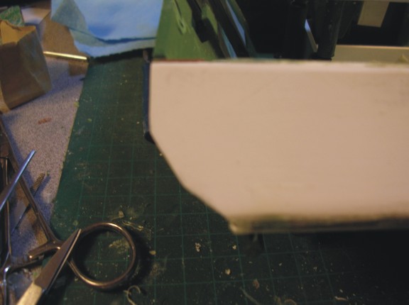
One of the biggest differences between the A&D and the G's was the slop of the side armour. On the A&D's it was 40 degees off center and on the G's 30 degrees. Low and behold if you take the angle from the top of the upper deck to the outside of the fender edge on the HL it is almost a perfect 40 degrees!
so using styrene sheets cut a couple of pieces to fit sanded the edges in a bit to fit on the angle better and tacked them on after filling all the holes for equipment mounfs with 2 part epoxy,
ATTACHMENTS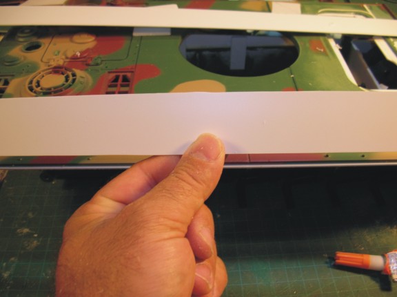 Panther A 46.jpg (39.98 KiB) Viewed 8 times
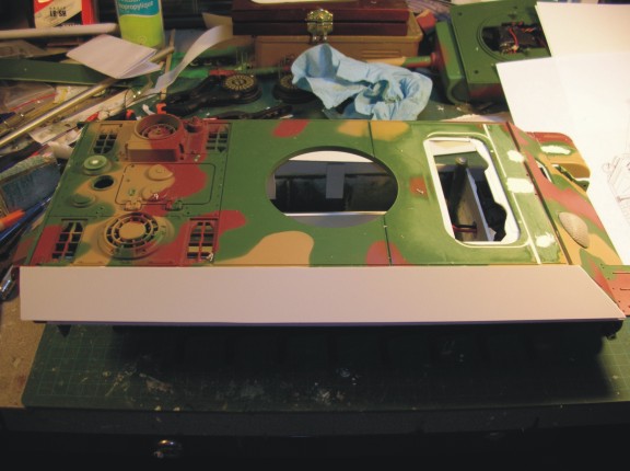 Panther A 47.jpg (51.58 KiB) Viewed 8 times
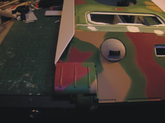 Panther A 48.jpg (35.77 KiB) Viewed 8 times
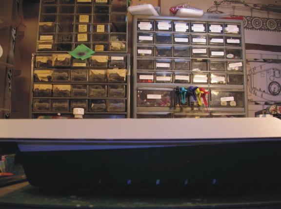 Panther A 49.jpg (55.53 KiB) Viewed 8 times
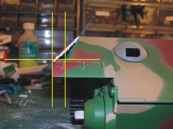
One of the biggest differences between the A&D and the G's was the slop of the side armour. On the A&D's it was 40 degees off center and on the G's 30 degrees. Low and behold if you take the angle from the top of the upper deck to the outside of the fender edge on the HL it is almost a perfect 40 degrees!
so using styrene sheets cut a couple of pieces to fit sanded the edges in a bit to fit on the angle better and tacked them on after filling all the holes for equipment mounfs with 2 part epoxy,
ATTACHMENTS
09-28-2014, 05:04 PM
#31
Hi Guys,
Sorry for the delay... I was sick with a head cold week before last and have been tied up doing family things the last 2 weekends but ready to get back at it a bit now.
When last we met I had shown how leaving the skirt armour ledge on the G let me make the 40 degree angle perfectly so we attached the sides and I closed off the front spaces with some styrene and then ran superglue around all the edges and taped them up to seal off the hollow triangular part. I also at this time refined the hull fit a little more with some tedious sanding of hull meet locations...
 Panther A 51.jpg (46.33 KiB) Viewed 1 time
Then I had the brilliant idea to pour resin into the hollow space to make sure it bonded to the hull and it would add firmness to the structure as well. Problem was I thought I had it all sealed but I had a couple of little spots that it leaked! But I dealt with it and the nice part is where the resin ran onto places like the front fenders, and down the sides a bit you can work it off carefully with an xacto knife. I didn't take any pics of the mess just this one looking down the hollow.
 Panther A 52.jpg (58.13 KiB) Viewed 1 time
While I was waiting for the resin to dry I started playing a little bit with the zim just for fun. I think the biggest issue is going to be the edges of things because this kit is made for the Tamiya kit not HL but like always we will make it work!
 Panther A 53.jpg (60.08 KiB) Viewed 1 time
After a couple of days the resin has set up enough that I can handle the hull no problem. So I turned my attention to the back engine deck and cut out the outside panels which are going to require a complete makeover. I also started putting in the styrene support that will hold the new panels in place.
 Panther A 54.jpg (46.21 KiB) Viewed 1 time
I then put the back plate back on and tightened it down in preperation for doing the rough finish of the rear hull...
 Panther A 55.jpg (54.99 KiB) Viewed 1 time
Sorry for the delay... I was sick with a head cold week before last and have been tied up doing family things the last 2 weekends but ready to get back at it a bit now.
When last we met I had shown how leaving the skirt armour ledge on the G let me make the 40 degree angle perfectly so we attached the sides and I closed off the front spaces with some styrene and then ran superglue around all the edges and taped them up to seal off the hollow triangular part. I also at this time refined the hull fit a little more with some tedious sanding of hull meet locations...
Then I had the brilliant idea to pour resin into the hollow space to make sure it bonded to the hull and it would add firmness to the structure as well. Problem was I thought I had it all sealed but I had a couple of little spots that it leaked!
While I was waiting for the resin to dry I started playing a little bit with the zim just for fun. I think the biggest issue is going to be the edges of things because this kit is made for the Tamiya kit not HL but like always we will make it work!
After a couple of days the resin has set up enough that I can handle the hull no problem. So I turned my attention to the back engine deck and cut out the outside panels which are going to require a complete makeover. I also started putting in the styrene support that will hold the new panels in place.
I then put the back plate back on and tightened it down in preperation for doing the rough finish of the rear hull...

 09-29-2014, 05:32 AM
#34
Yep, unable to see the photos in your last post. Like what I have seen so far!!!!

Like what I have seen so far!!!!
09-29-2014, 08:34 AM
#35
I think it worked this time! I will edit the other one right out...
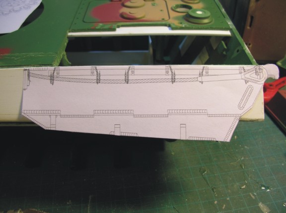
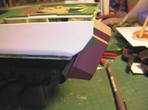
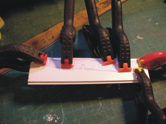
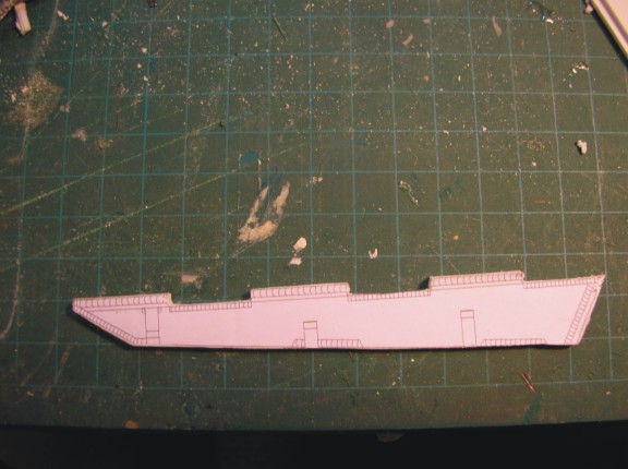
So to add the vertical piece of armour at the rear, first, I again used my drawings and cut out the whole side piece and tacked it on the side in position.
 Panther A 56.jpg (42.66 KiB) Viewed 8 times
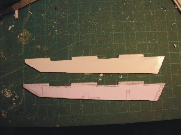
Then I drew the cut out edge on the styrene and cut it. I elongated it a little because the paper is only 2D so you have to extend the cut lines a little to compensate for the real thing. I pulled it off and reversed the paper to do the other side. Then did the cuts
 Panther A 57.jpg (40.29 KiB) Viewed 8 times
 Panther A 58.jpg (35.97 KiB) Viewed 8 times
Next I test fitted the rear storage boxes to check fit
 Panther A 59.jpg (42.77 KiB) Viewed 8 times
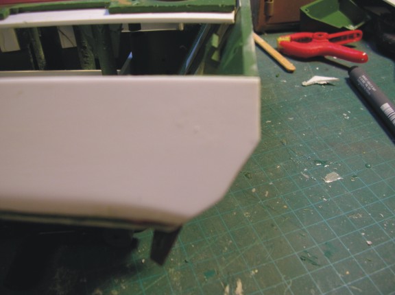
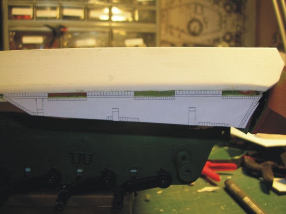
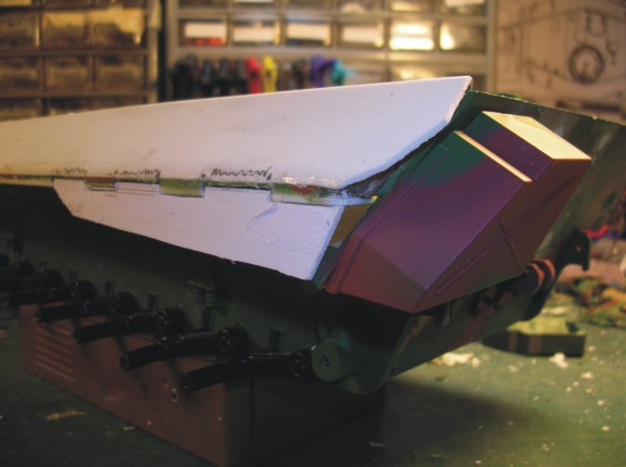
I then cut out the actual lower vertical plate by itself and tacked it on to see the fit and position
 Panther A 60.jpg (38.91 KiB) Viewed 8 times
I am going to fill this small opening with styrene no issues.
 Panther A 62.jpg (35.99 KiB) Viewed 8 times
Next tacked 2 pieces of styrene together and tacked the paper on so that I make 2 identical pieces at one time.
 Panther A 63.jpg (49.09 KiB) Viewed 8 times
Cut with a dremel and filed down a bit and then split them apart
 Panther A 64.jpg (52.61 KiB) Viewed 8 times
 Panther A 65.jpg (48.2 KiB) Viewed 8 times
Marked the lower hull and notched it out and fitted in and glued for the moment. Because this will all be covered by zim it doesn't have to look too pretty...
 Panther A 66.jpg (41.79 KiB) Viewed 8 times
"There are things in Russia which are not as they seem..."
Georgy Konstantinovich Zhukov

dgsselkirk Sergeant Posts: 575Joined: Mon Oct 15, 2012 8:57 pmLocation: Kitchener, Ontario, Canada Top
[HR][/HR] by dgsselkirk � Sun Sep 28, 2014 11:01 pm
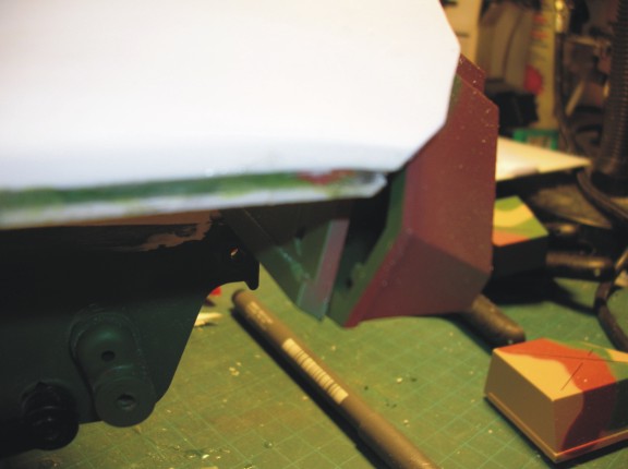
And one more shot I will be building a box behind the vertical plate extending in to the hull like on the real thing and that will give the vertical plate strength against any whacks the vertical plate might take battling.
 Panther A 67.jpg (36 KiB) Viewed 8 times
So to add the vertical piece of armour at the rear, first, I again used my drawings and cut out the whole side piece and tacked it on the side in position.
Then I drew the cut out edge on the styrene and cut it. I elongated it a little because the paper is only 2D so you have to extend the cut lines a little to compensate for the real thing. I pulled it off and reversed the paper to do the other side. Then did the cuts
Next I test fitted the rear storage boxes to check fit
I then cut out the actual lower vertical plate by itself and tacked it on to see the fit and position
I am going to fill this small opening with styrene no issues.
Next tacked 2 pieces of styrene together and tacked the paper on so that I make 2 identical pieces at one time.
Cut with a dremel and filed down a bit and then split them apart
Marked the lower hull and notched it out and fitted in and glued for the moment. Because this will all be covered by zim it doesn't have to look too pretty...
"There are things in Russia which are not as they seem..."
Georgy Konstantinovich Zhukov
dgsselkirk Sergeant Posts: 575Joined: Mon Oct 15, 2012 8:57 pmLocation: Kitchener, Ontario, Canada Top
[HR][/HR]
And one more shot I will be building a box behind the vertical plate extending in to the hull like on the real thing and that will give the vertical plate strength against any whacks the vertical plate might take battling.
10-03-2014, 04:09 AM
#36
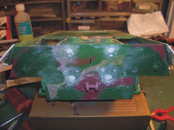
More epoxy fill! 
So on the underside of D's and A's the vertical extension had a box like structure going back toward the lower hull so I decided to stiffen it all up by filling the box with epoxy. It also added some more stiffness to the plate running under the upper hull that I put in.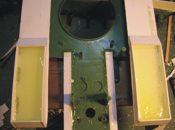 Panther A 68.jpg (49.11 KiB) Viewed 9 times
 Panther A 69.jpg (50.92 KiB) Viewed 9 times
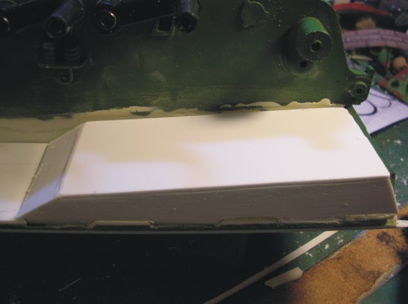
I then put the cover over and that was done! I think it looks pretty good and if flushes up nice with the back plate so far.
 Panther A 70.jpg (35.45 KiB) Viewed 9 times
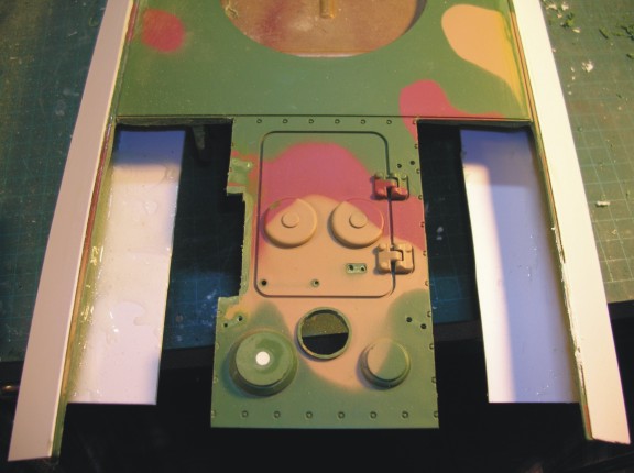
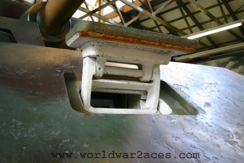
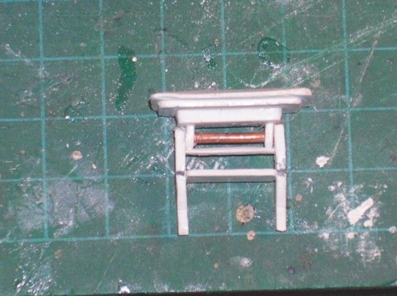
While I let this harden up I thought I would turn my attention to one of the centerpieces of this tank the front drivers vision port. I referenced a pic of the Littlefield Panther and a pic from worldwar2aces.com . to build it up from scratch:
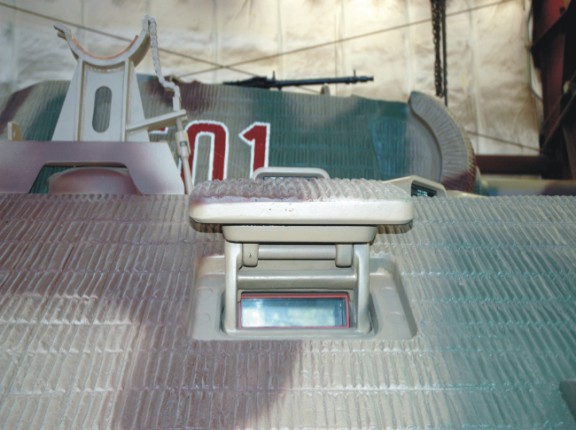 vision port 2.jpg (56.94 KiB) Viewed 9 times
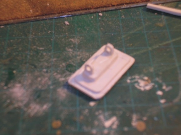
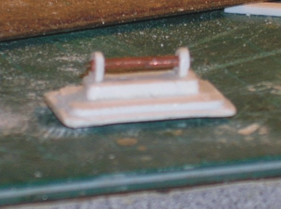
So started with the cover I had built earlier and put a little edge around it and added the hinge block and the 2 eyelets. Sorry, some of these pics are a little blurry!
 Panther A 71.jpg (40.6 KiB) Viewed 9 times
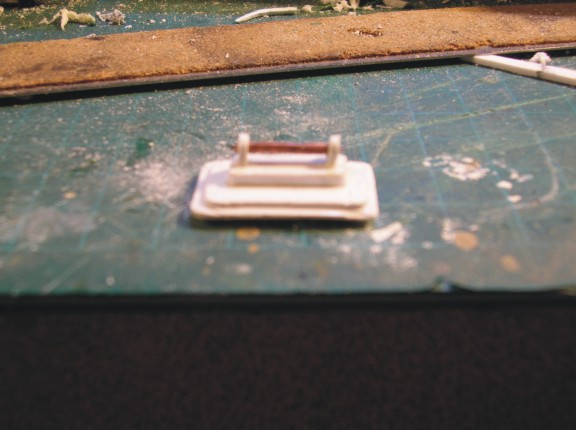
Then took a piece of little copper tubing and stuck a paperclip through the center to mount the cover's arms on a bit.
 Panther A 72.jpg (50.49 KiB) Viewed 9 times
 Panther A 73.jpg (51.4 KiB) Viewed 9 times
 Panther A 74.jpg (46.39 KiB) Viewed 9 times
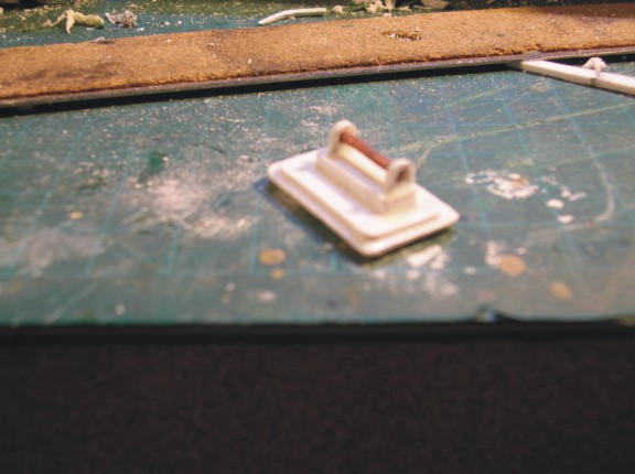
Here the arms are stuck on
 Panther A 75.jpg (66.21 KiB) Viewed 9 times
So on the underside of D's and A's the vertical extension had a box like structure going back toward the lower hull so I decided to stiffen it all up by filling the box with epoxy. It also added some more stiffness to the plate running under the upper hull that I put in.
I then put the cover over and that was done! I think it looks pretty good and if flushes up nice with the back plate so far.
While I let this harden up I thought I would turn my attention to one of the centerpieces of this tank the front drivers vision port. I referenced a pic of the Littlefield Panther and a pic from worldwar2aces.com . to build it up from scratch:
So started with the cover I had built earlier and put a little edge around it and added the hinge block and the 2 eyelets. Sorry, some of these pics are a little blurry!
Then took a piece of little copper tubing and stuck a paperclip through the center to mount the cover's arms on a bit.
Here the arms are stuck on
10-03-2014, 04:11 AM
#37
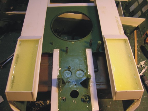
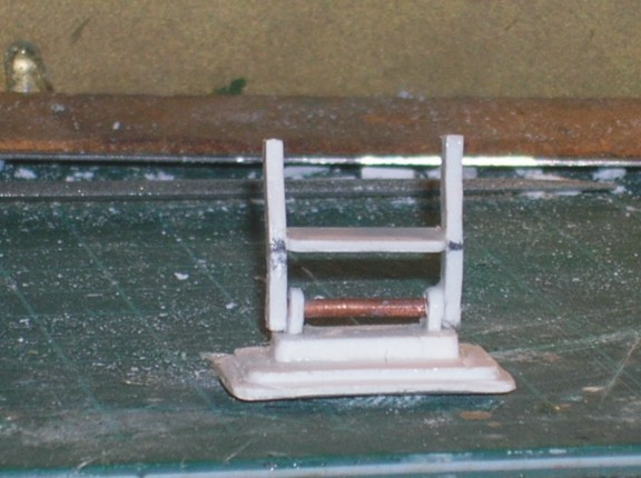
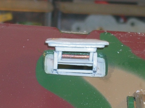
I then added the "shelfs" that box in the vision block (which I will make later)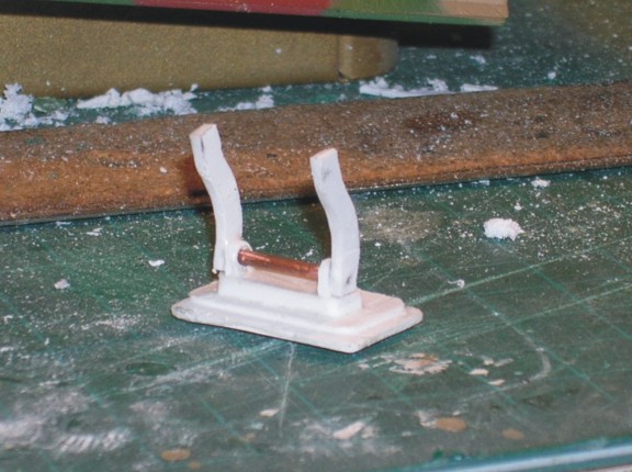 Panther A 76.jpg (68.35 KiB) Viewed 9 times
 Panther A 77.jpg (57.92 KiB) Viewed 9 times
 Panther A 78.jpg (61.08 KiB) Viewed 9 times
 Panther A 79.jpg (63.91 KiB) Viewed 9 times
and here are some pics of it test fitted into the hole. I have made the tolerances tight enough that I think I will be able to close it when I want. This will be important when I go to do the camo pattern because I will want it closed for the pattern to go over it!
 Panther A 80.jpg (41.22 KiB) Viewed 9 times
 Panther A 81.jpg (48.36 KiB) Viewed 9 times
 Panther A 82.jpg (39.08 KiB) Viewed 9 times
and here are some pics of it test fitted into the hole. I have made the tolerances tight enough that I think I will be able to close it when I want. This will be important when I go to do the camo pattern because I will want it closed for the pattern to go over it!
10-03-2014, 04:38 AM
#38
The drivers vision block cover looks great!!! Do you have a photo from the inside of the huul to show how you attached it? Thanks, Rudy
Thanks, Rudy
10-03-2014, 05:55 AM
#39
Hi Rudy,
Thanks for the kind words I haven't actually mounted it yet. I made the fit nice and tight so for now I just squeeze the little arms together slightly and push it into the hole. This lets me still push it right through to close it. Once I am done done and paint is all done then I think I will secure it in the open position but who knows, I may get ambitious and make it function. Somebody suggested servo but my electronic skills aren't up to that!
Thanks for the kind words
I haven't actually mounted it yet. I made the fit nice and tight so for now I just squeeze the little arms together slightly and push it into the hole. This lets me still push it right through to close it. Once I am done done and paint is all done then I think I will secure it in the open position but who knows, I may get ambitious and make it function. Somebody suggested servo but my electronic skills aren't up to that!
10-03-2014, 07:34 AM
#40
Senior Member
Join Date: May 2009
Location: Evans, GA
Posts: 1,506
Likes: 0
Received 0 Likes
on
0 Posts
Hi Rudy,
Thanks for the kind words I haven't actually mounted it yet. I made the fit nice and tight so for now I just squeeze the little arms together slightly and push it into the hole. This lets me still push it right through to close it. Once I am done done and paint is all done then I think I will secure it in the open position but who knows, I may get ambitious and make it function. Somebody suggested servo but my electronic skills aren't up to that!
Thanks for the kind words
I haven't actually mounted it yet. I made the fit nice and tight so for now I just squeeze the little arms together slightly and push it into the hole. This lets me still push it right through to close it. Once I am done done and paint is all done then I think I will secure it in the open position but who knows, I may get ambitious and make it function. Somebody suggested servo but my electronic skills aren't up to that!  10-05-2014, 06:48 PM
#42
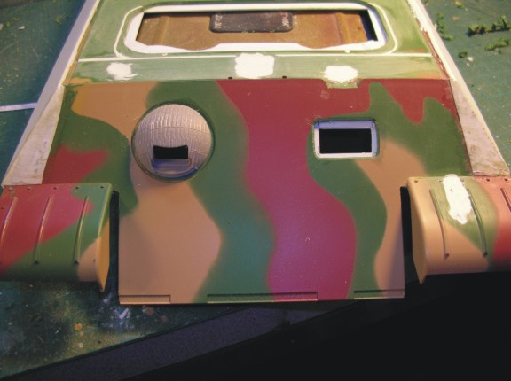
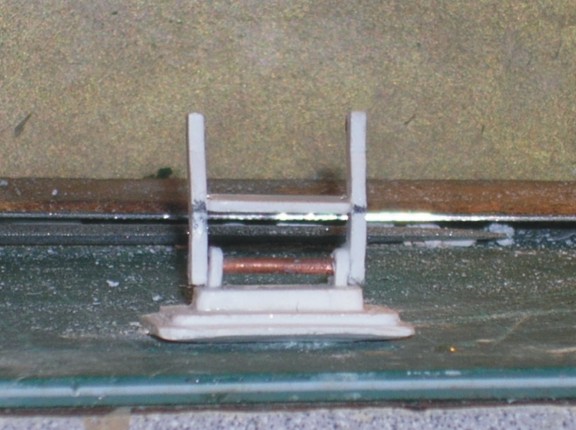
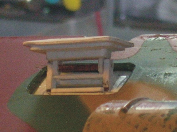
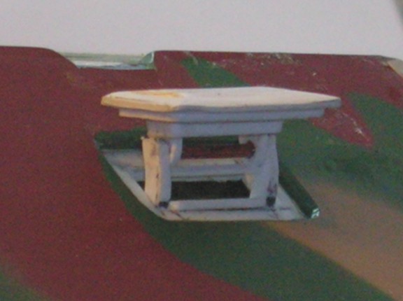
Well boys, the vision port is going to be static, sorry!  Once I put the vision port glass block in to test fit there is no real way to make it function as the glass block cannot rotate to go back inside the tank which I would need it to do. On the real thing my understanding is you push the cover up into position and then slide the glass block up into position. Of course I can't do that so fixed it is.
On the otherhand with the periscope glass block in it does look very accurate in that it fills the hole completely like the real thing...
Attachments vision port 3.jpg (44.08 KiB) Not viewed yet
 vision port 4.jpg (44.86 KiB) Not viewed yet
 vision port 5.jpg (44.43 KiB) Not viewed yet
 vision port 6.jpg (41.59 KiB) Not viewed yet
On the otherhand with the periscope glass block in it does look very accurate in that it fills the hole completely like the real thing...
Attachments
10-05-2014, 06:49 PM
#43
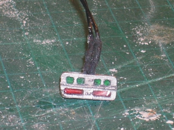
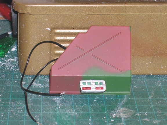
While messing around with the back end and relocating the large stowage boxes I thought I would fit the Notek convoy light on the bottom of the bin. I got this little light a couple of months ago from Germany. I took it apart and installed "glass" (clear plastic) and paintd the top green and the bottom red. On the real thing there is a flap that flips up and down to cover one or the other light panels. Depending on what It looks like when I light it up I might put it on but if it looks cool with all the colours lit I will simulate the cover ripped off!
 Panther A 83.jpg (70.48 KiB) Not viewed yet
 Panther A 84.jpg (71.29 KiB) Not viewed yet
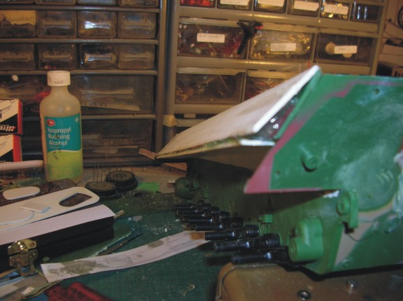
Next I wanted to add the final bracing to the upper hull and that is done. I used an aluminum strip screwed into the sides to help pull them a little closer and super glue under the ceter section. Once that was done somemore 2 part epoxy the secure it permanently...
 Panther A 85.jpg (50.44 KiB) Not viewed yet
 Panther A 86.jpg (53.77 KiB) Not viewed yet
Next I wanted to add the final bracing to the upper hull and that is done. I used an aluminum strip screwed into the sides to help pull them a little closer and super glue under the ceter section. Once that was done somemore 2 part epoxy the secure it permanently...
10-06-2014, 06:17 AM
#45
While messing around with the back end and relocating the large stowage boxes I thought I would fit the Notek convoy light on the bottom of the bin. I got this little light a couple of months ago from Germany. I took it apart and installed "glass" (clear plastic) and paintd the top green and the bottom red. On the real thing there is a flap that flips up and down to cover one or the other light panels. Depending on what It looks like when I light it up I might put it on but if it looks cool with all the colours lit I will simulate the cover ripped off!
 Panther A 83.jpg (70.48 KiB) Viewed 13 times
 Panther A 84.jpg (71.29 KiB) Viewed 13 times
Next I wanted to add the final bracing to the upper hull and that is done. I used an aluminum strip screwed into the sides to help pull them a little closer and super glue under the ceter section. Once that was done somemore 2 part epoxy the secure it permanently...
 Panther A 85.jpg (50.44 KiB) Viewed 13 times
 Panther A 86.jpg (53.77 KiB) Viewed 13 times
"There are things in Russia which are not as they seem..."
Georgy Konstantinovich Zhukov

dgsselkirkSergeant Posts: 591Joined: Mon Oct 15, 2012 8:57 pmLocation: Kitchener, Ontario, Canada
 by dgsselkirk � Sun Oct 05, 2014 11:43 pm
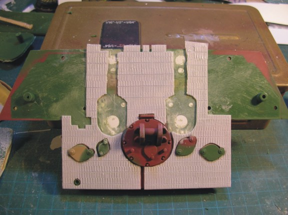
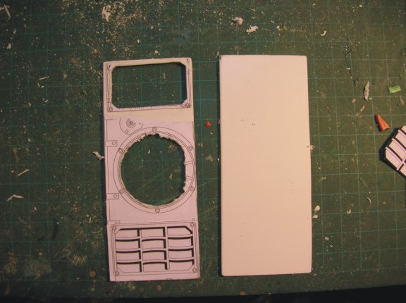
so now started work on the back deck. This is going to take a while!
the pictures pretty much speak for themselves. Cut 2 panels, glued on scale drawing,
 Panther A 87.jpg (44.66 KiB) Viewed 13 times
rough cut the holes,
 Panther A 88.jpg (56.92 KiB) Viewed 13 times
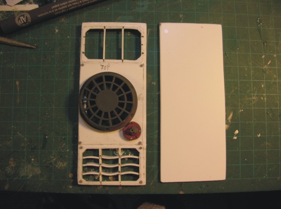
Started building and fitting styrene for the grills, attached the circular fan covers I got from the famous "pantiger" upper hull I bought for peanuts. These are actually the correct covers for the "A" and are very,very close to correct scale.
 Panther A 89.jpg (50.3 KiB) Viewed 13 times
I used paper thin styrene to represent the thin bolt on plates for each section and added bolts in position
 Panther A 90.jpg (45.63 KiB) Viewed 13 times
 Panther A 91.jpg (44.97 KiB) Viewed 13 times
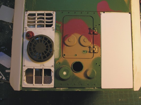
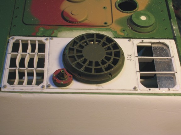
I remember it was either on this forum or one of the others there was a big argument about how many bolts were on the antenna housing on the Panther. Some said 3, some said 4.
From my research on the D's and A's if the antenna housing had a little edge rounded to go around the adjacent fan covers it has 3 bolts. If the antenna housing was perfectly round (As on most G's) it had 4. So as you can see here I did 3 which matches the Munster Panther "A" which I am using for a lot of reference on the decks.
 Panther A 92.jpg (49.49 KiB) Viewed 13 times
 Panther A 93.jpg (48.25 KiB) Viewed 13 times
So I figure it will take me a week to finish these back deck sections and this weekend is Canadian Thanksgiving so we are going away so it may be a couple of weeks before I do a new update....
It's coming together though! Most of the really tough structural stuff is done. I know the angle of the bottom glacis plate is wrong but I really don't want to mess with the lower hull too much so I think I will leave it for now. Sorry rivet counters!
Next I wanted to add the final bracing to the upper hull and that is done. I used an aluminum strip screwed into the sides to help pull them a little closer and super glue under the ceter section. Once that was done somemore 2 part epoxy the secure it permanently...
"There are things in Russia which are not as they seem..."
Georgy Konstantinovich Zhukov
dgsselkirkSergeant Posts: 591Joined: Mon Oct 15, 2012 8:57 pmLocation: Kitchener, Ontario, Canada
so now started work on the back deck. This is going to take a while!
the pictures pretty much speak for themselves. Cut 2 panels, glued on scale drawing,
rough cut the holes,
Started building and fitting styrene for the grills, attached the circular fan covers I got from the famous "pantiger" upper hull I bought for peanuts. These are actually the correct covers for the "A" and are very,very close to correct scale.
I used paper thin styrene to represent the thin bolt on plates for each section and added bolts in position
I remember it was either on this forum or one of the others there was a big argument about how many bolts were on the antenna housing on the Panther. Some said 3, some said 4.
From my research on the D's and A's if the antenna housing had a little edge rounded to go around the adjacent fan covers it has 3 bolts. If the antenna housing was perfectly round (As on most G's) it had 4. So as you can see here I did 3 which matches the Munster Panther "A" which I am using for a lot of reference on the decks.
So I figure it will take me a week to finish these back deck sections and this weekend is Canadian Thanksgiving so we are going away so it may be a couple of weeks before I do a new update....
It's coming together though! Most of the really tough structural stuff is done. I know the angle of the bottom glacis plate is wrong but I really don't want to mess with the lower hull too much so I think I will leave it for now. Sorry rivet counters!
10-06-2014, 06:26 AM
#46
Looks good so far. You could always save up and buy a Asiatam metal lower hull to replace the one you have.
Happy Canadian Thanksgiving!!! Rudy
Happy Canadian Thanksgiving!!! Rudy
Last edited by MAUS45; 10-06-2014 at 06:29 AM.

 10-07-2014, 07:30 PM
#50
Well, I wasn't going to post anything for a while but after about 5 hours work I finally finished one side panels with the grills! Yippee!!!
 Panther A 97.jpg (54.7 KiB) Not viewed yet
 Panther A 98.jpg (49.43 KiB) Not viewed yet
Now I still have to do some finishing on them but it's just minor detals. Before I did the one end I also test fitted my screens made out of a kitchen splatter cover for a frying pan. They will have small frames fitted around them out of copper wire or styrene I haven't decided.
 Panther A 96.jpg (56.5 KiB) Not viewed yet
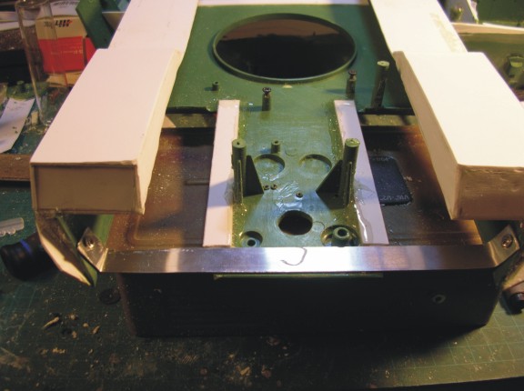
Also I re-did the air intake hole. Here is the original way it was from my other Panther
 air intake hole original.jpg (52.43 KiB) Not viewed yet
 air intake hole original 2.jpg (37.88 KiB) Not viewed yet
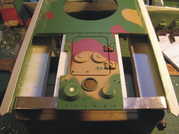
and my replacement
 Panther A 94.jpg (58.2 KiB) Not viewed yet
 Panther A 95.jpg (61.07 KiB) Not viewed yet
While grills were drying I decided to see if my Notek light worked so I plugged it into my Sherman LED in it so even though I did put in green glass it still comes up red so I think I will put the cover on the top the way it would have been done on the real thing.
 Panther A 99.jpg (41.11 KiB) Not viewed yet
 Panther A 100.jpg (35.05 KiB) Not viewed yet
That's it for now!
Now I still have to do some finishing on them but it's just minor detals. Before I did the one end I also test fitted my screens made out of a kitchen splatter cover for a frying pan. They will have small frames fitted around them out of copper wire or styrene I haven't decided.
Also I re-did the air intake hole. Here is the original way it was from my other Panther
and my replacement
While grills were drying I decided to see if my Notek light worked so I plugged it into my Sherman LED in it so even though I did put in green glass it still comes up red so I think I will put the cover on the top the way it would have been done on the real thing.
That's it for now!